


- New
- Out-of-Stock


DIY Component Tester images
A DIY, Arduino-based component tester for transistors, resistors, capacitors and more!
Kit includes PCB, pre-loaded Arduino, tricky-to-source connectors, and a 16x2 backlit LCD screen.
This product is the unpopulated PCB and a few components only - full assembly, soldering, and fitting in an enclosure will be required.
A DIY, Arduino-based component tester for transistors, resistors, capacitors and more!
Look, I know you can buy component testers, and I know some of them are coming in a reasonable prices these days. But that doesn't always matter to some of us. Some of us like to get hands-on and love the feeling of building something for ourselves. This project is one of those - it's fun to put together, infinitely useful, and something you can tweak, edit and build on in the future.
Multiple connectors to test components:
Large 16x2 character, LCD backlit screen with clear values and pin identifiers. 12mm tactile push button to reset and re-test. Powered by USB through the onboard Arduino USB socket.
A lot of the parts needed for this project are easy to get hold of, or if you regularly build pedals you'll likely have. However, a few bits were slightly harder to find so they'll be included in your purchase. When you order this PCB, we'll also send you:
| Part # | Value | Component |
|---|---|---|
| R1 | 680r | Metal film resistor |
| R3 | 680r | Metal film resistor |
| R5 | 680r | Metal film resistor |
| R2 | 470k | Metal film resistor |
| R4 | 470k | Metal film resistor |
| R6 | 470k | Metal film resistor |
| R7 | 22k | Metal film resistor |
| 2x 15-way single row socket | Arduino connections | |
| 1x 8+8 double row socket | Component pin sockets | |
| 4x | 6mm | Nylon PCB spacers |
| 8x | M3 6mm | Nylon screws (trimmed slightly) |
This project takes inspiration (and source code) from this build by Creative Techos.
The resistors are all used to help the Arduino define some base values which then drive the accuracy of the tester. Because of this, I'd advise metal film resistors as they tend to have improved tolerances and you might want to grab a batch and measure them with a multimeter to find those that measure as close to the required values as possible.
Step 1 - add the resistors.
Step 2 - add the LCD screen. Fit the right-angle connector to the LCD pins and line it up but don't solder it yet. Fix it in place using the spacers between the LCD and the PCB and the M3 screws. Once fixed, solder the connector from the rear of the PCB.
Step 3 - add the button.
Step 4 - add the pin connectors, just making sure they're as straight as possible.
Step 5 - add the Arduino - go careful but it should line up perfectly and slide into the connectors easily. Push firmly to click it into place.
Step 6 - power up with a USB cable and give it a quick test. Everything should power up straight away and you'll get a loader message on the LCD screen. Pressing the button will give you an error that there's a missing (or broken) component. Give it a test with some components you know the values of - resistors are good - and validate the results.
Step 7 - optionally run a calibration. Using wires or trimmed component legs, connect test sockets 1, 2 and 3 together and press to test. The device will detect that all 3 sockets are shorted and will run a diagnostic and calibration test. Once complete, you should experience more accuracy in readings.
In addition to these examples, you can also test MosFETS, thyristors, and inductors.
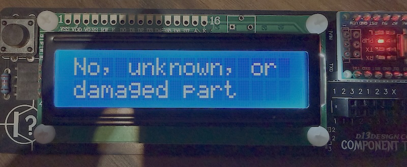
The tester can't identify the provided component, or suspects it may be missing.
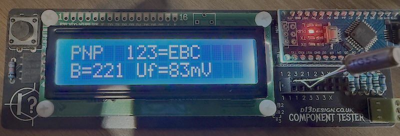
The tester confirms this transistor as PNP and identifies pin 1 as the Emitter, pin 2 as the Base, and pin 3 as the Collector. The hFE reads at ~221.
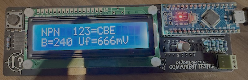
The tester confirms this transistor as NPN and identifies pin 1 as the Collector, pin 2 as the Base, and pin 3 as the Emitter. The hFE reads at ~240.
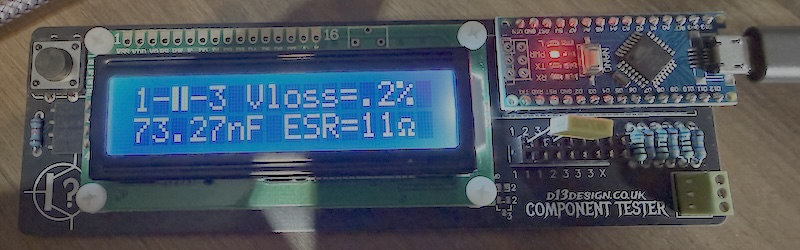
The tester confirms this component is a capacitor, connected between pins 1 and 3, with a value of 73nF (actual component was 68nF).
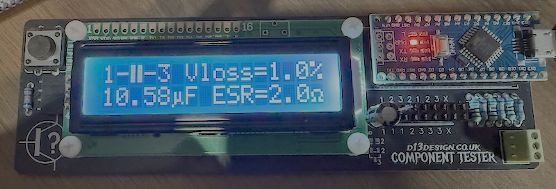
The tester confirms this as an electrolytic capacitor, connected between pins 1 and 3, with a value of 10.5uF (actual component was 10uF).
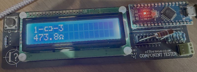
The tester confirms this as a resistor measuring 473.8 ohms, connected between pins 1 and 3 (actual component was 470r)
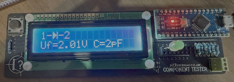
The tester confirms this as a diode, connected between pins 1 and 2 (1 being the Anode+ and 2 being the Cathode-) and a forward voltage of 2.01v.
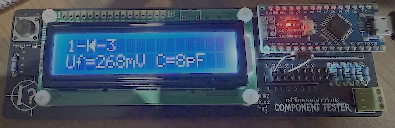
The tester confirms this as a diode, connected between pins 1 and 3 (1 being the Cathode- and 3 being the Anode-) and a forward voltage of 268mv.
Occasionally, the tester can report incorrect values when running with no component installed - typically it will detect some capacitance or resistance between pins and provide a reading. If this occurs, or if you just want to calibrate the tester, then you can short the three pins together and press the button. Self test mode will begin and the device will calibrate. This tends to resolve any problems and returns things to a fully working state. If issues continue, or if you want to play with the software a bit more, then you can re-flash the Arduino using the code project found at https://drive.google.com/file/d/1jCziEUAKc78mH5Md9VgCyUTUBu0OrBwq/view?usp=drive_link


Comments (0)
Your review appreciation cannot be sent
Report comment
Report sent
Your report cannot be sent